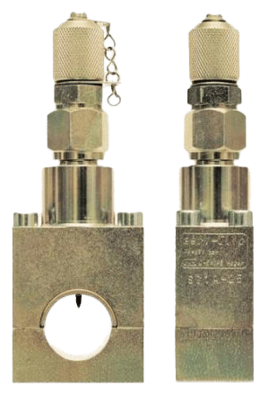
Serv Clip® Type 1
for Pressurized Pipes
Hydraulic Pipe measuring point Serv-Clip® Type 1 with 1/4″ screw for hydraulic and gear oils. Installation with jaw/screw wrench only.
- Quick and cheap installation (only 3 minutes)
- Measurement without switching off the system
- No cutting tubes, cleaning, contamination of fluids
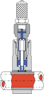
How Does It Work?
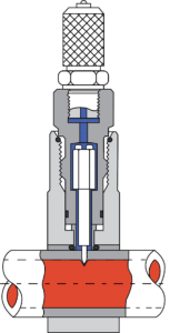
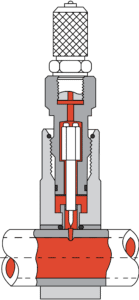
The patented pressure measuring clip is simply screwed onto the cleaned surface of the pressurized hydraulic tube. It is not necessary to interrupt the operation of the plant. A specially shaped steel needle is inserted through the wall of the tube above the screw head. The screw head is then screwed back. The created hole is then open and it is possible to measure the pressure immediately. This connection is simple, quick and safe to install. The procedure only takes a few minutes. No special tools are required to install the Serv-Clip. The system is completely leakproof. Any pollution of the hydraulic liquid is impossible. It is not necessary to dismantle the measuring clip on completion of the measuring procedure in order to save costs. The operational safety of the hydraulic system is maintained.
Step One:
Place in Position

Step Two:
Screw Down
Step Three:
Insert
Step Four:
Measure
In 4 simple steps you can:
- Measure pressure
- Take oil samples
- Bleed lines / Install pressure gauges
- Install pressure sensors or pressure switches
- Carry out particle measurements
Technical
Information
Tolerances of the outer diameter of the pipe according to DIN 2391 |  |
Pipe recommendation for steel made Serv-Clips | Seamless drawn steel pipes made out of ST 35.4 material or pre-treated basic material ST 37.4 according to DIN 1630. Condition when supplied NBA (normalising, bright annealed) with outer pipe diameter tolerances according to DIN 2391, maximum hardness: HRB 75. Construction dimensions of the Serv-Clip are adapted to the pipes and tolerances according to DIN 2391. |
Pressure capacity | PB 630 (the indications with regard to pressure and safety are based on the installation according to this data leaflet) |
Working Temperature | – 40… + 120 °C (Steel) |
| PB 630 (the indications with regard to pressure and safety are based on the installation according to this data leaflet)  |
Pressure reduction | Required pressure reduction due to the material in comparison to catalogue details in the case of increased or reduced temperatures. If there are divergent definitions for permissible pressures, safety margins, temperatures and, if necessary, applicable pressure reductions due to standards, regulations or approvals for specific applications, the information provided by them is obligatory. Nominal pressures (PN) and working pressures (PE) detained in the catalogue are max. permissible working pressures including pressures peaks, whereby the temperature limits and pressure reductions detailed in the table above must be taken into consideration. Functional safety under stationary load: Types with PB indications : 2.5 times |